 Witt Sensoric GmbH
Tore sich bewegen
Safety edges
Application
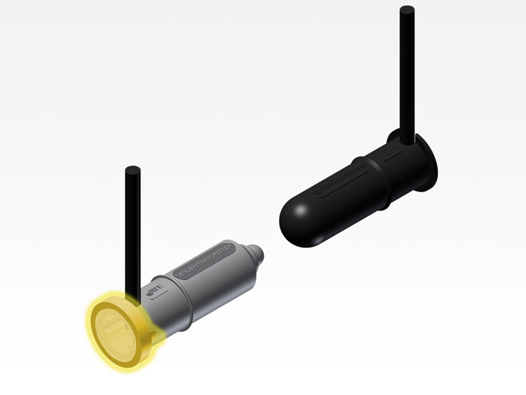
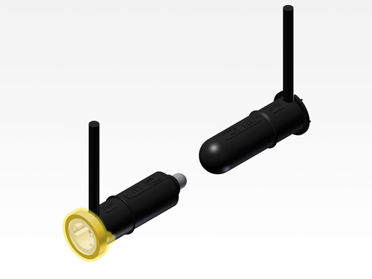
The LOW-POWER-SIGNAL is a 3rd generation optoelectronic safety edges. Our many years of experience with optical optoelectronic safety edges and modern market-requirements have been innovatively merged in this product.
Diagnostic display
The components are always checked after connection to the power. These include the quality of the rubber compound, gate width, deflection, contamination, etc. The result of the test reading is displayed in the form of a blink-code with a range of 1 to 3 impulses.
1 LED-flash = ideal conditions
2 LED-flashes = good conditions
3 LED-flashes = operational limit reached
Three flashes indicate that operational limit has been reached. The rubber profile should be checked for damages and the light path should be checked for contaminants. To repeat the diagnosis, briefly disconnect the optoelectronic safety edge from the power.
Switching status
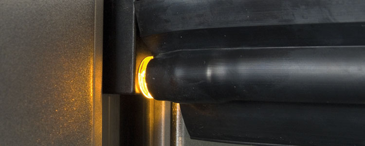
After diagnosis, the LOW-POWER-SIGNAL mode comes into operation. When the light-path is disrupted the yellow LED will illuminate.
Easy service
Thanks to the diagnostic display, the assembler can judge the operational safety of the optoelectronic safety edge and the rubber profile. The switching status display can, when necessary, help identify any faults.
Optical system
The new optical system allows for a larger gate width and a better switch performance with transverse deflections.
Universally usable
The LOW-POWER-SIGNAL adjusts itself with the help of its patented "duo-switch" detection method to the spiral cable and the battery power. This happens automatically while the connected operating voltage is being registered. This results in optimal conditions for the respective operating situations.
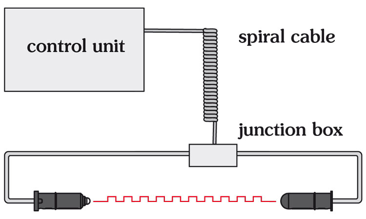
When the LOW-POWER-SIGNAL is attached directly to the controls via a spiral cable, it will work like a standard optoelectronic safety edge. It can be directly connected to any modern control with an OSE-input.
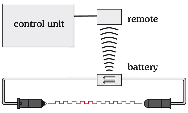
With battery powered control units, the LOW-POWER-SIGNAL will set itself up automatically. The power consumption is significantly reduced to maximize battery life.
Overview
| SIGNAL | LOW-POWER-SIGNAL | |
|---|---|---|
| operating voltage | 10...16VDC | battery mode: 3...6V spiral cable: 9...27V |
| current consumption | spiral cable, ca. 40mA | battery mode: typ. 1,6mA spiral cable: typ. 3,8mA |
| range | 1...12m | 1...12m |
| diagnostics display | 1...16 flashes | 1...3 flashes |
| signal frequency | 900Hz | battery mode: typ. 400Hz spiral cable mode: typ. 900Hz |
Note: Table is horizontally scrollable


